Power Through Earth
Earth Transmission
Wirelessly sending power through the earth is a project funded by the National Science Federation (NSF). The purpose of this experiment is to send power to sensors in a field an and to determine the characteristics and viability of sending power within the earth.
The principle of earth transmission is similar to the single wire wireless power transfer characteristics of a coil. The earth completes a path between the top and bottom electrode of the system.
Placing a current through the top electrode of the well will cause a current that will transmit into the earth and propagate across the skin layer of the earth. This is a very similar phenomenon like seen in a Zenneck wave. This allows for the current being sent into the well to travel over long distances reaching to potentially a few mile.



Transmission Site
Shipley Farm Site
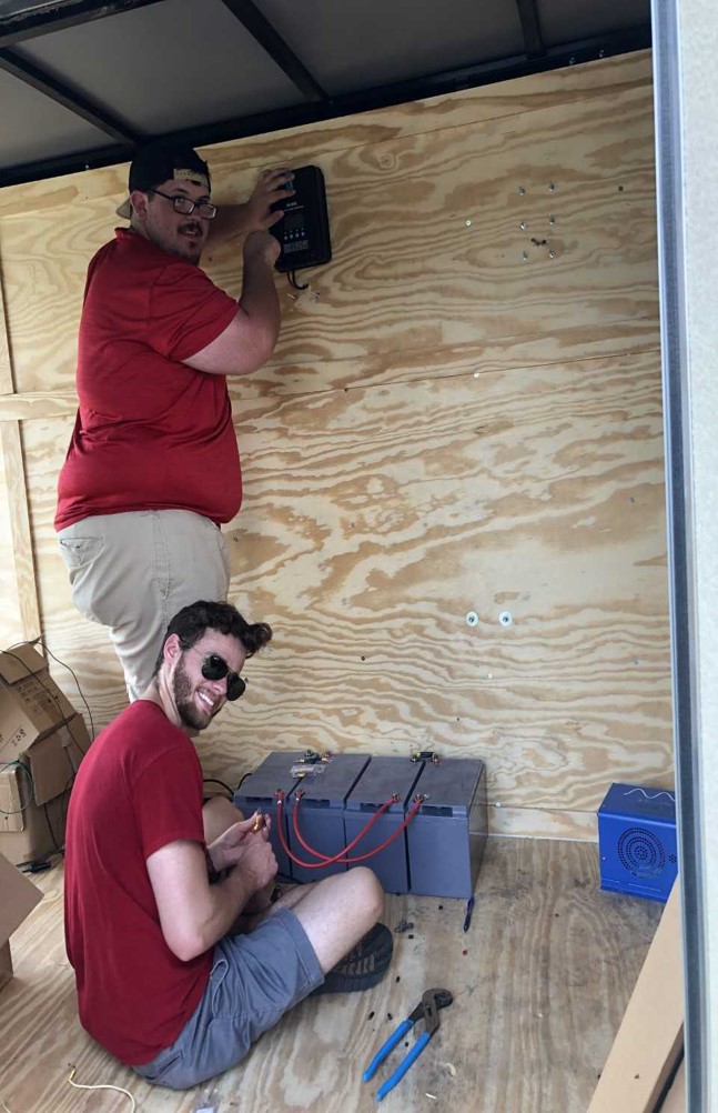
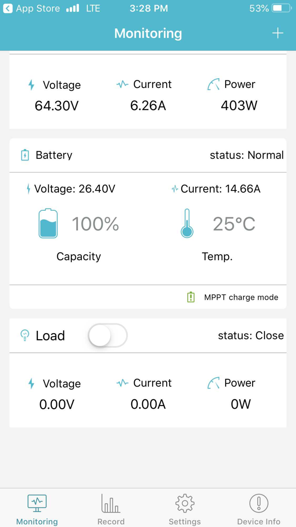
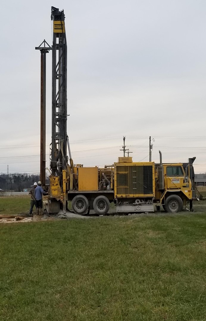
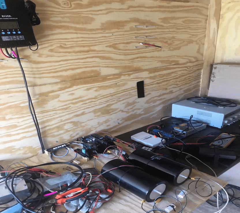
The location of the wireless power transmission site is located at Shipley Farm Site near Tennessee Tech University. The location consist of a 550 feet deep well and a trailer for test equipment storage and an off-grid source of power.

The Underground Well
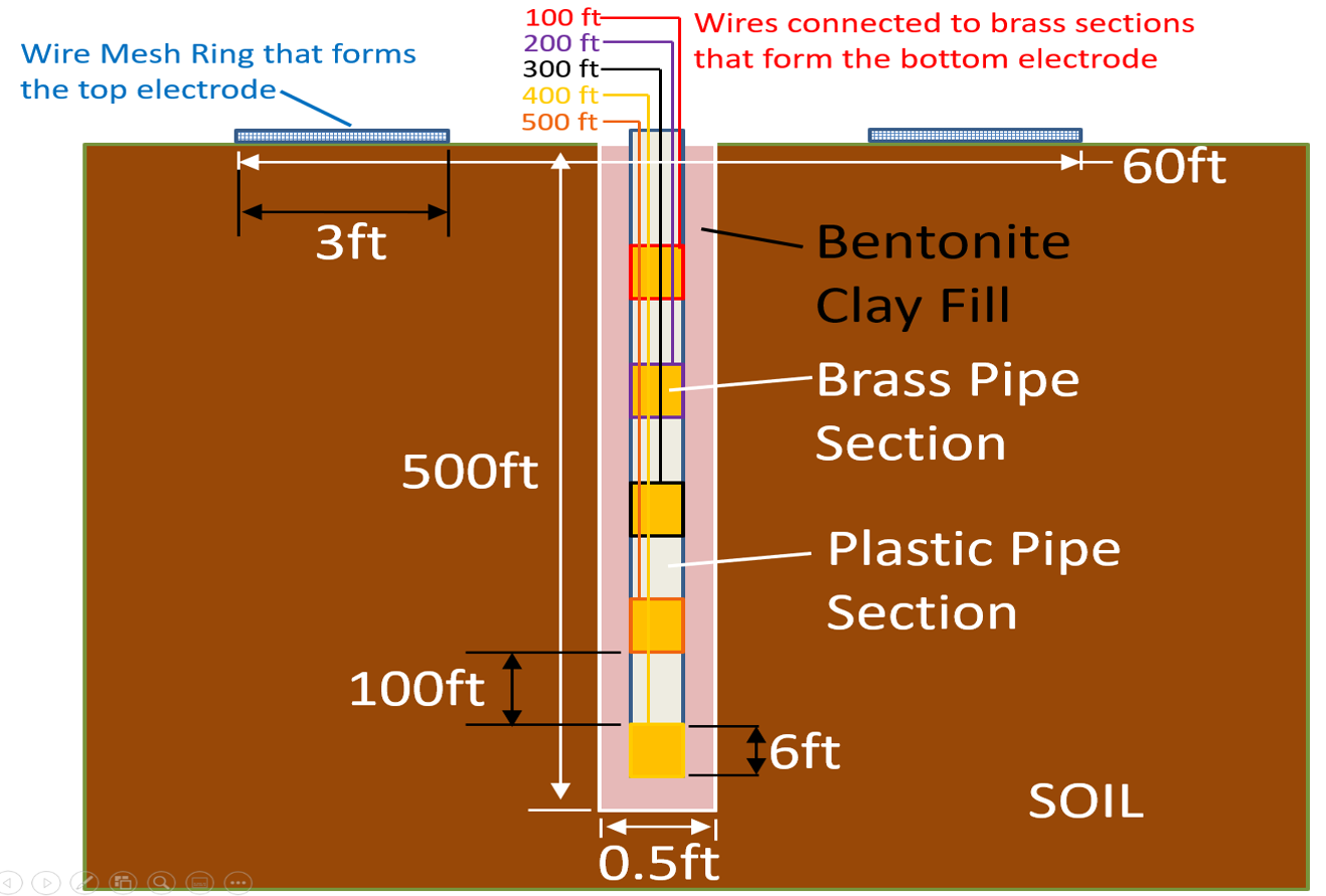
The underground well is designed with 5-6’ copper pipes. The pipes are placed every 100 feet apart, and a chicken wire fencing is placed around the well to create a top electrode surface to complete the path to each of the copper pipes. This will be used to evaluate the efficiency and viability of different depths to transmit power through the earth.
Signal Analysis
Impedance Measurements
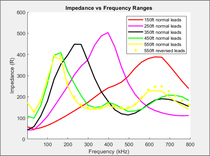
The impedance of the ground that is between the top and bottom electrode of the well. The depth of the copper tube will lower the frequency as you get deeper into the earth.
Voltage vs Distance
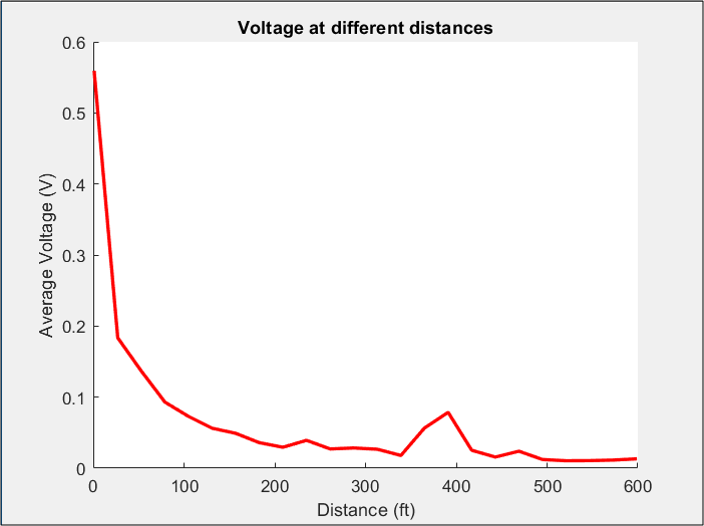
The voltage dissipation drops off very fast about 100 feet out. The voltage then drops slow and it continues for a very long distance. The wave characteristics are similar to Zenneck wave and Surface wave propagation.
Power Applications
Luxating Inverter Design (MARX-Inverter)
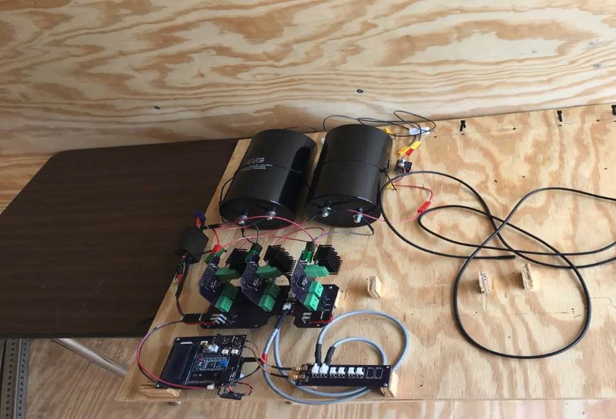
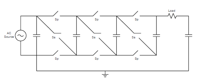
Margret is based on a Marx inverter design. The capacitors are switched from series to parallel and vise versa to achieve higher voltages.
The device is comprised of:
- 3 modules are located on the luxating inverter design.
- Each module is 3 switches with 2 capacitors to charge up.
- All modules are connected to a sequential switching device.
Earth Currents
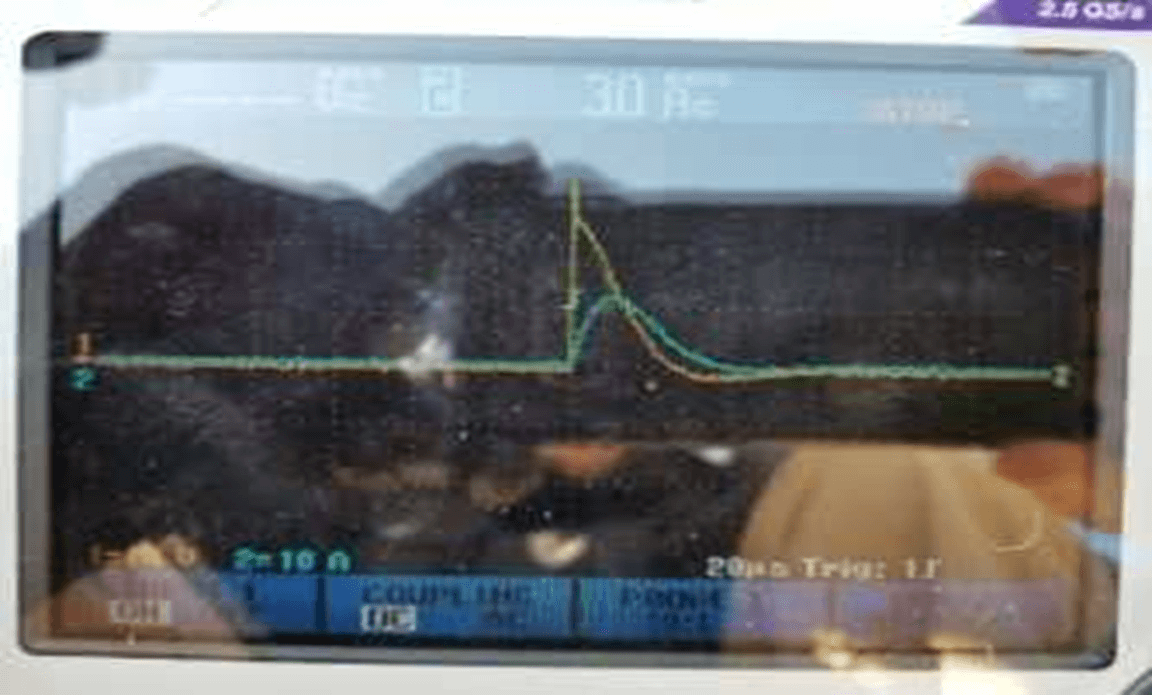
The underground well picked up a random 30Hz and 180 Hz signal that are being considered as earth currents. The earth currents are believed to be the currents of the natural environment like lightning during a storm. The transfer of power using the well is highly dependent on the input current of Margret into the earth. As the current increases the voltage output at further distances rise.
