Smart Grid Lab
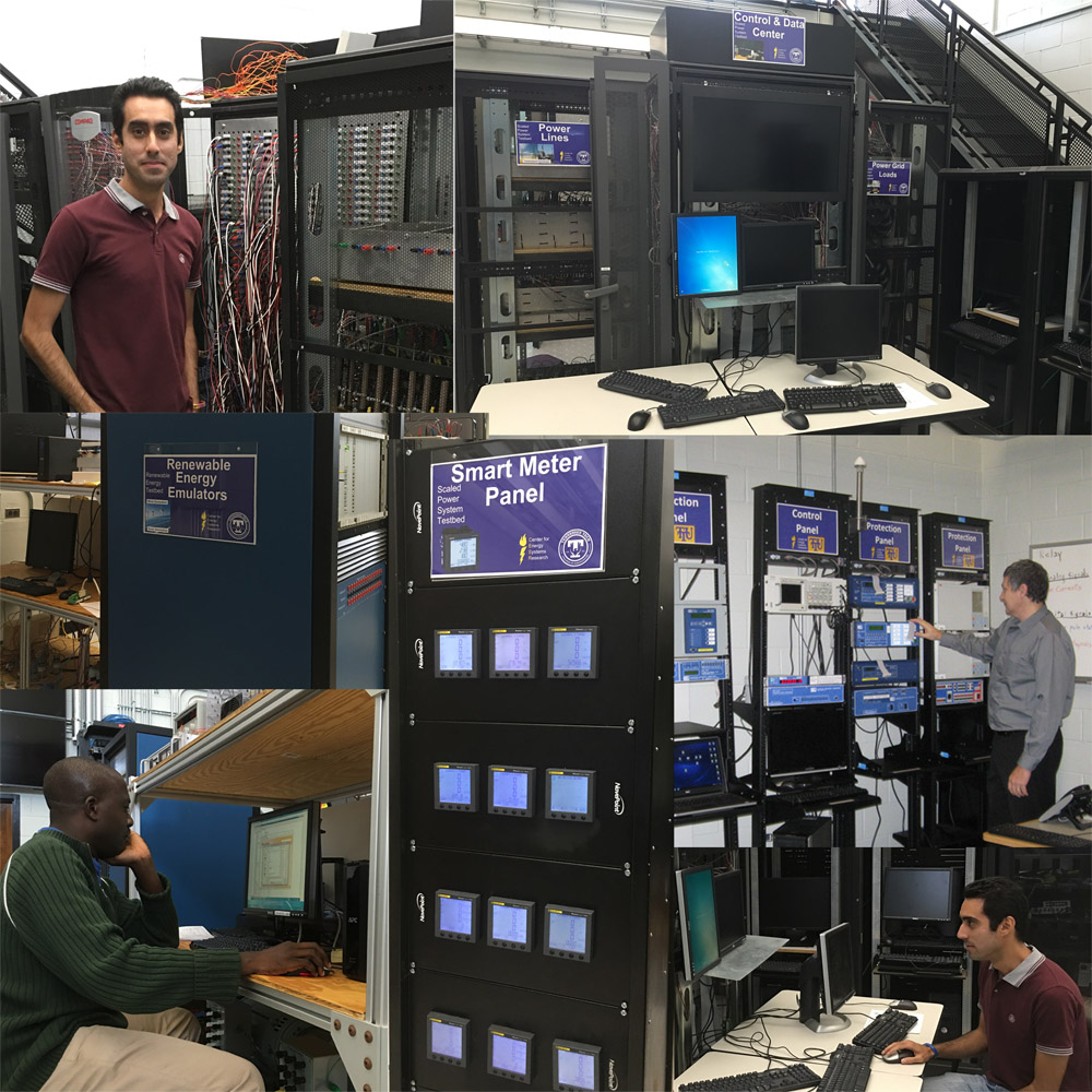
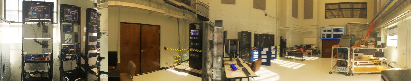
Composite View
Introduction
The smart grid laboratory was created at Tennessee Tech in response to a set of Grand Challenges presented to a team of researchers. It recognizes that smart grid research should not be conducted purely as simulation but must utilize real hardware/software combinations to guarantee researchers deal with real-world limitations and that solutions that are developed be realistic, practical, and functional.
Smart Grid means many things to many people but let's say it is an electric power system that employs modern power electronics, advanced instrumentation, secure communication, and information technologies so that it is robust against disturbances with the least likelihood of blackouts and is efficient in energy transfer between sources and loads at the lowest cost to consumers.
GRAND CHALLENGES (Power Grid)
- Make the grid self-healing from power disturbance events.
- Operate the grid resiliently against physical and cyber-attacks.
- Enable active participation by consumers in demand response.
- Provide quality power for 21st century needs.
- Accommodate all generation and storage options in the grid.
- Optimize assets and operate the grid efficiently.
Scale Power Grid Testbed
Presented here is a brief list of actual equipment, stations, or sub testbeds within the laboratory which could be utilized for a variety of new research projects.
- 3 large generators (>10 Hp) (Several more are available in an unfinished state)
- 5 small generators (<1 Hp)
- Transmission line emulators (Pi circuits) Can emulate transmission lines or distribution lines depending on lump circuit values chosen
- Resistance loads
- Motor loads
- 12 Smart Meters set up for instrumentation and protection
- PLC control of contactors utilizing Alarm signals from meters
- More meters available for future expansion
- National Instruments DAQ for currents, voltages, generator speeds, switch control, etc.
- Custom developed SCADA system based on NI LabVIEW Data Supervisory Control (DSC)
- Wind emulator
- Solar emulator
- Real-time digital simulators
- Custom developed intelligent agents for resilient grid operation
- Computer controlled switches/contactors for smart grid construction
- Synchronized connection of various power sources
- Researcher created faults and disturbances
- Researcher or algorithm disconnection of loads, sources, power line sections
- Substation Testbed
- Sensor development and testing
- Unmanned Autonomous Systems (UAS) for inspection and preventive maintenance purposes of the physical assets of the real-world power grid.
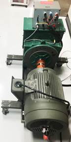
Generator and Primemover
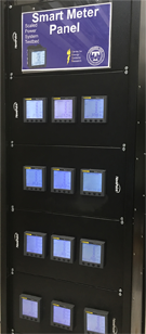
Smart Meters
Aging Testbed and Sensor Development
Efficient use of disposable resources in a power system contributes to Smart operation of a grid. Condition based rather than age based use of resources such as distribution transformers requires accurate knowledge of leftover age and inclusion of appropriate sensors. Experiments have been conducted at Tennessee Tech to develop ageing guidelines for the distribution transformers based on IEEE standards. Accelerated ageing tests and optical sensors for furanic compounds (2-FAL) in the insulating oil are being pursued. Loss of life as a result of short term overloads on a distribution transformer in a smart grid could then be evaluated.
Electrical Substation Testbed
At the Smart Grid Laboratory, the Electrical Substation Testbed (Figure 1) allows real-time simulations of power systems with hardware in-the-loop, such as protective relays and communication devices. The Electrical Substation Testbed is based on the state-of-the-art digital signal processing technology, by non-real-time and real-time simulators. In the computer real-time simulation, the power system is carried out with digital real-time simulation of the electric power system, reproducing the voltage and current waveforms, with the desired accuracy that are representative of the behavior of the real power system being modeled.
The Electrical Substation Testbed has five rack panels with a computer real-time simulator, satellite synchronize clock, communication processor, protective relays, and relay test systems (Figure 2). Smart grid applications are explored by using protection, control, communication and measurement functions of protective relays. Protection, control and communication systems for electrical substations can be evaluated for large power systems by using the computer real-time simulator. Actually, an adaptive overcurrent protection for a microgrid based on programmable logic and math operators has been performed, by validating the selectivity, speed and reliability. In the future, we want to upgrade our Electrical Substation Testbed with a Synchrophasor and SCADA system that will be applied in power system control and monitoring activities for research and education.
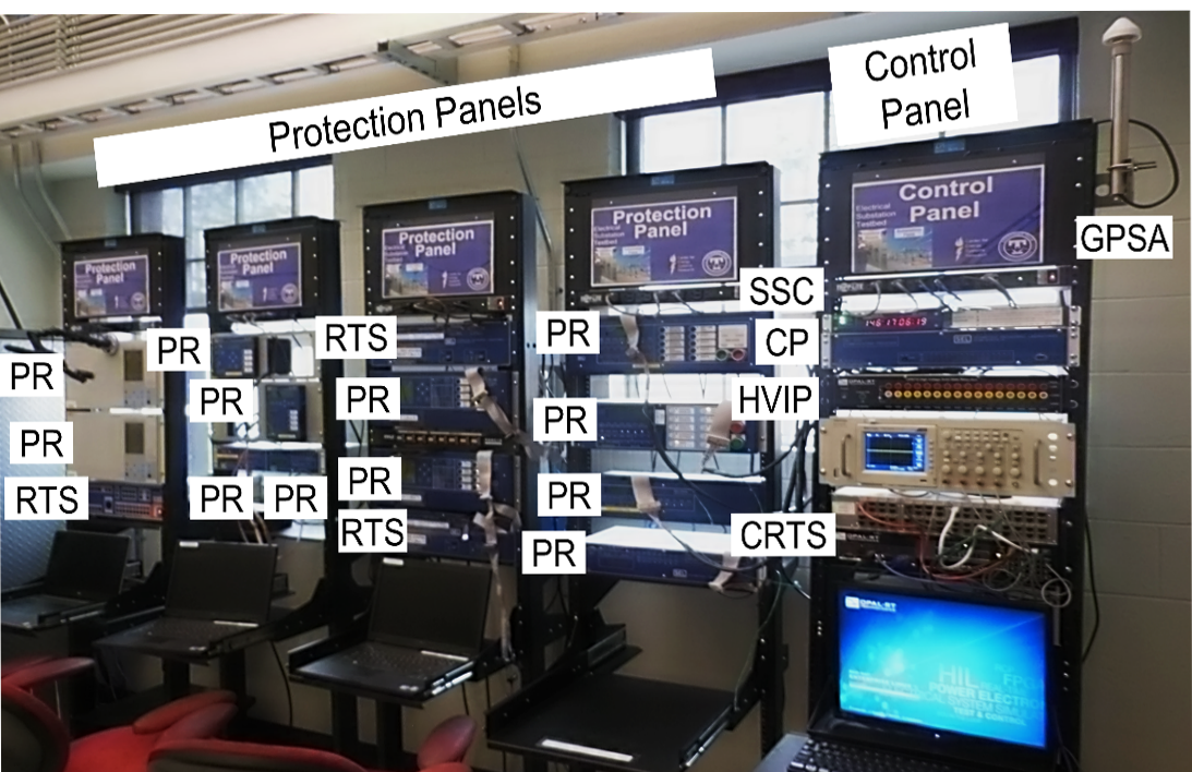
- RTS – Computer Real-time simulator
- HVIP – High voltage interface panel
- SSC – Satellite synchronize clock
- CP – Communication processor
- GPSA – Global positioning system antenna
- PR – Protective relay
- RTS – relay test system
Laboratory Research Capabilities
Presented here is a brief bullet list of research capabilities utilizing the smart grid laboratory.
- Power grid emulation
- Study propagation of disturbances
- Study synchrophasors on power grid testbed
- Study intelligent means of recovering from faults, i.e. self-healing
- Solar Emulators
- Study grid stability due to intermittency
- Study non-inertial effects on grid behavior
- Study synthesis of inertial effects
- Study reactive power synthesis in inverter design
- Wind Emulators
- Study grid stability due to intermittency
- Study reactive power effects and synthesis
- Islanding mitigation/prevention
- Island creation
- Load shedding
- Protection
- Frequency Control
- Intelligent automatic generation control with high penetration of renewables
- Microgrids
- UAS charging/autonomous navigation/inspection
A series of example project will give ideas as to the types of projects that can be conducted in this laboratory.
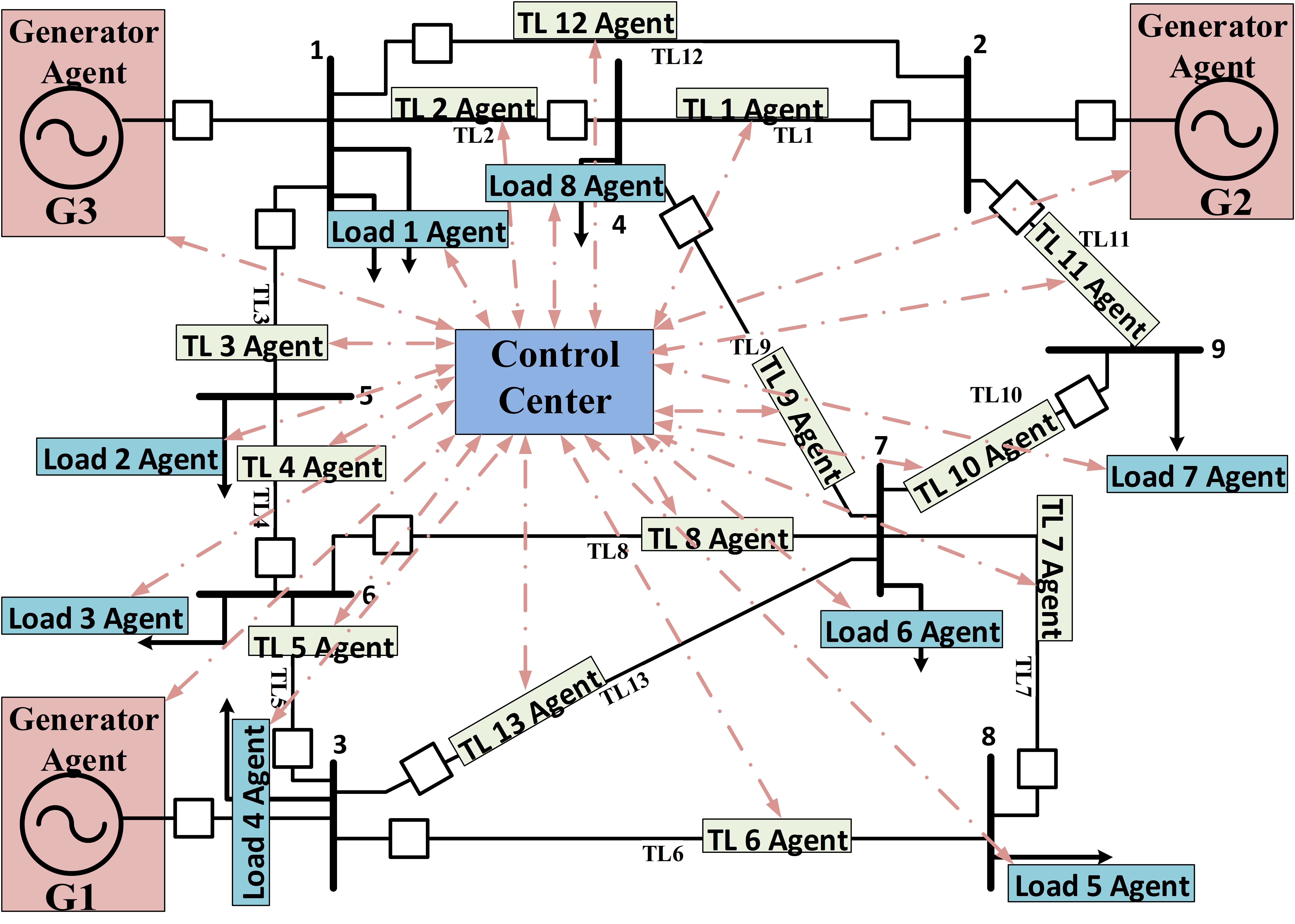
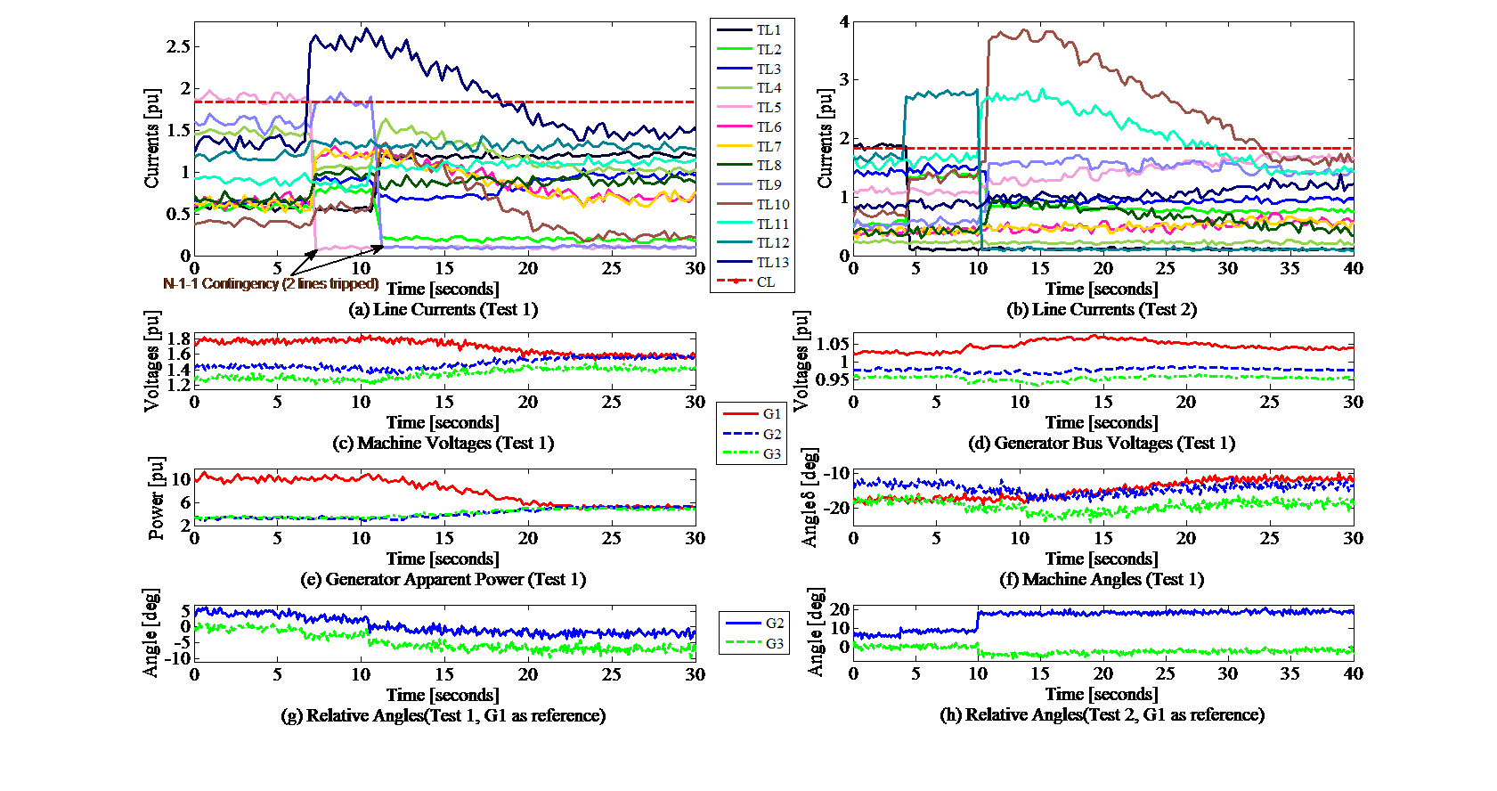
Example Project: Cascading Failure Prevention
A power grid such as the one shown in Figure 6 was created in the laboratory. A Transmission line failure was emulated by closing a switch feeding one of the transmission lines. Figure 7 shows the resulting currents in the transmission line after the failure, a subsequent transmission line failure, and successful power redistribution due to intelligent agents which changed phase angles of generators relative to each other until no transmission lines were overloaded.
Example Project: Preventative Maintenance Facilitated by UAS Inspection
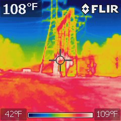
An active area of research in the smart grid laboratory is autonomous inspection of power grid assets for preventative maintenance purposes. The image on the left showing the warmth of a substation transformer under normal operating conditions with no abnormal hot spots.
- Autonomous navigation
- Self-Charging (From the power line or special docking stations along the line)
- Inspection (optical techniques, rf techniques, machine vision techniques),
Example Project: Reactive power strategy testing
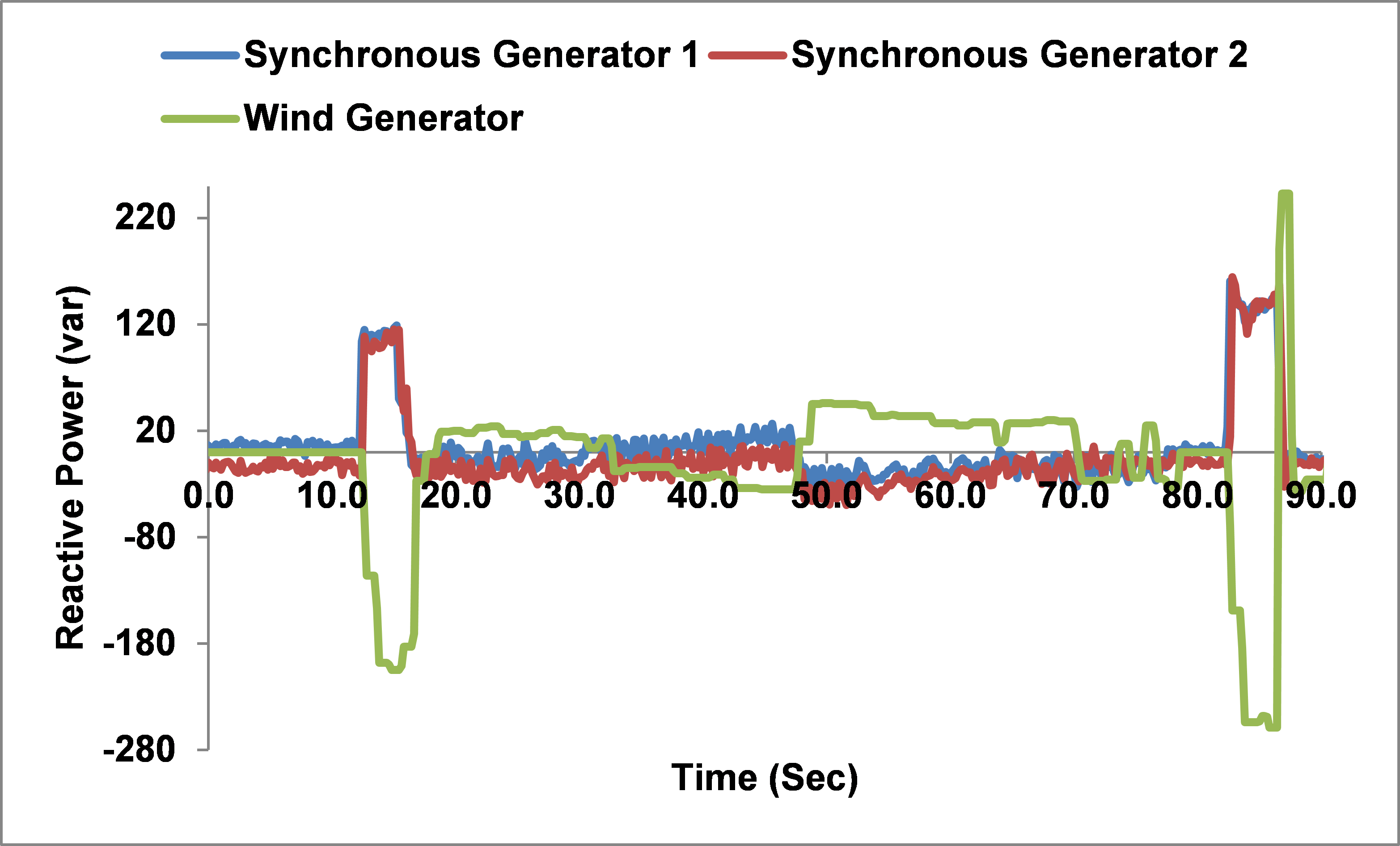
A student tested a strategy for reactive power compensation utilizing wind speed as the trigger for engaging banks of capacitors. In the example the initial wind is zero and once a threshold wind is met the turbine engages. It also has a very high speed wind disengage self-protection mechanism which is evident near the end of the test run where it disengages at very high speed wind and then reengages once the wind drops below the threshold. This capacitor engagement strategy works well in the middle of the test but does nothing for the dynamic engage, disengage portions of operation. Of course an algorithm based on reactive power needs, not wind speed is clearly required.
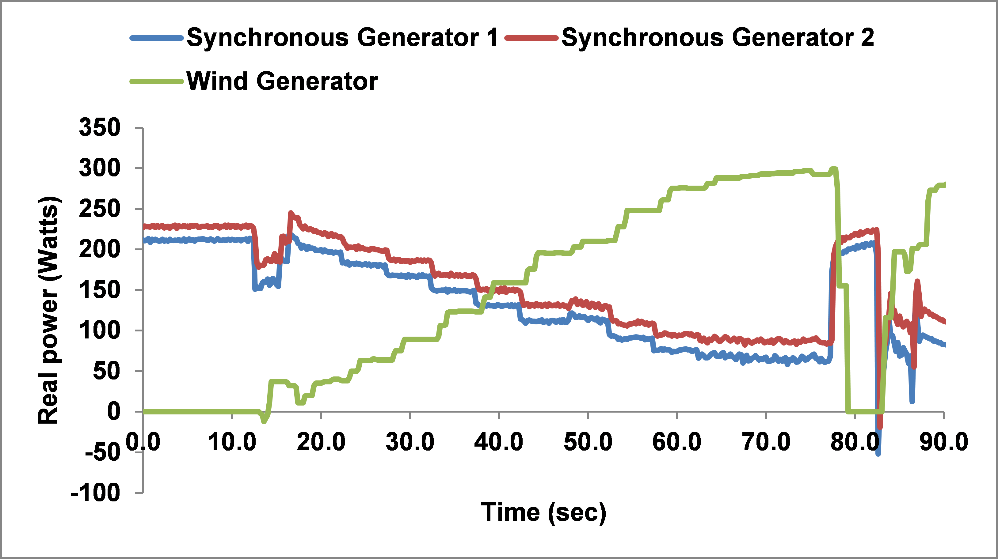
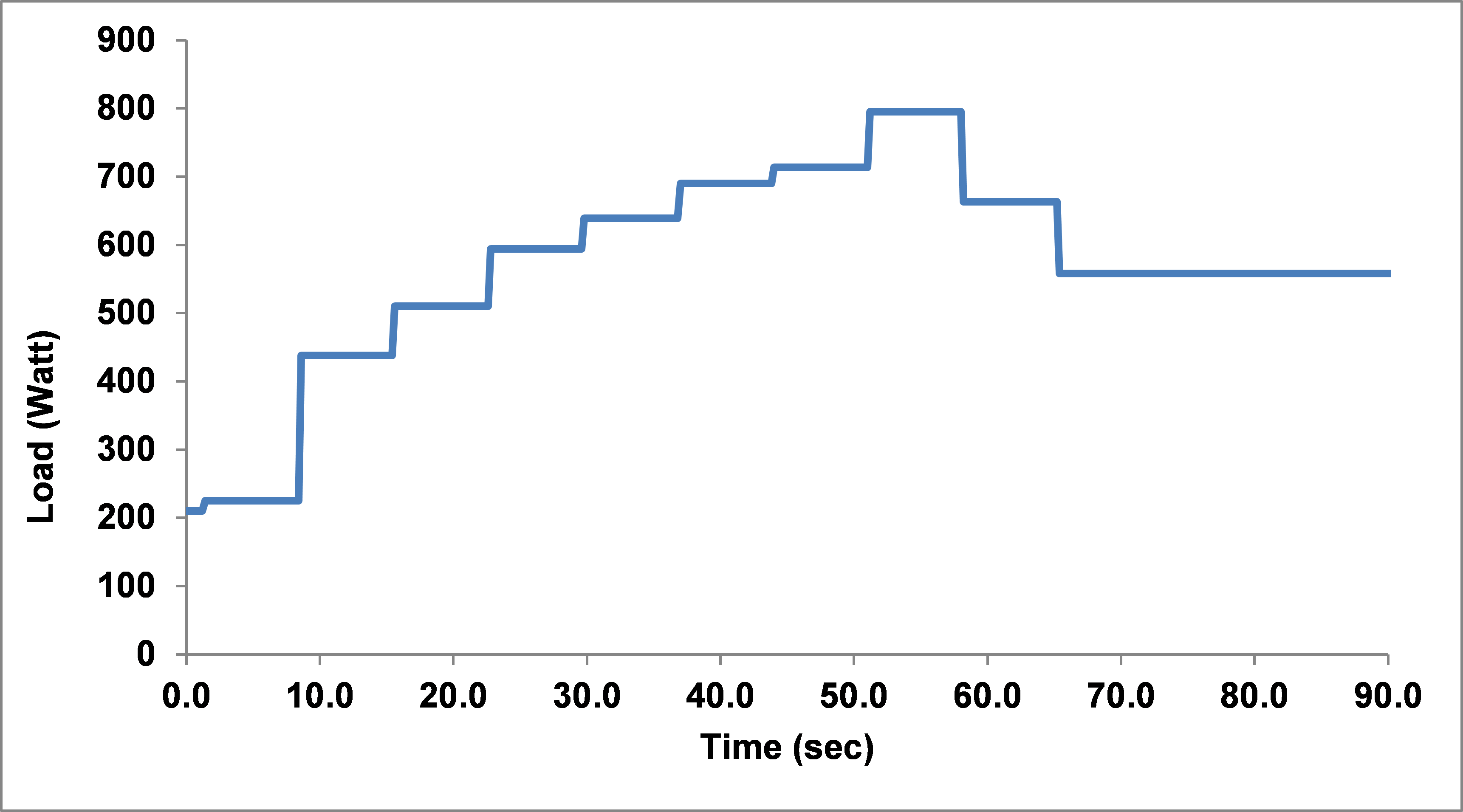
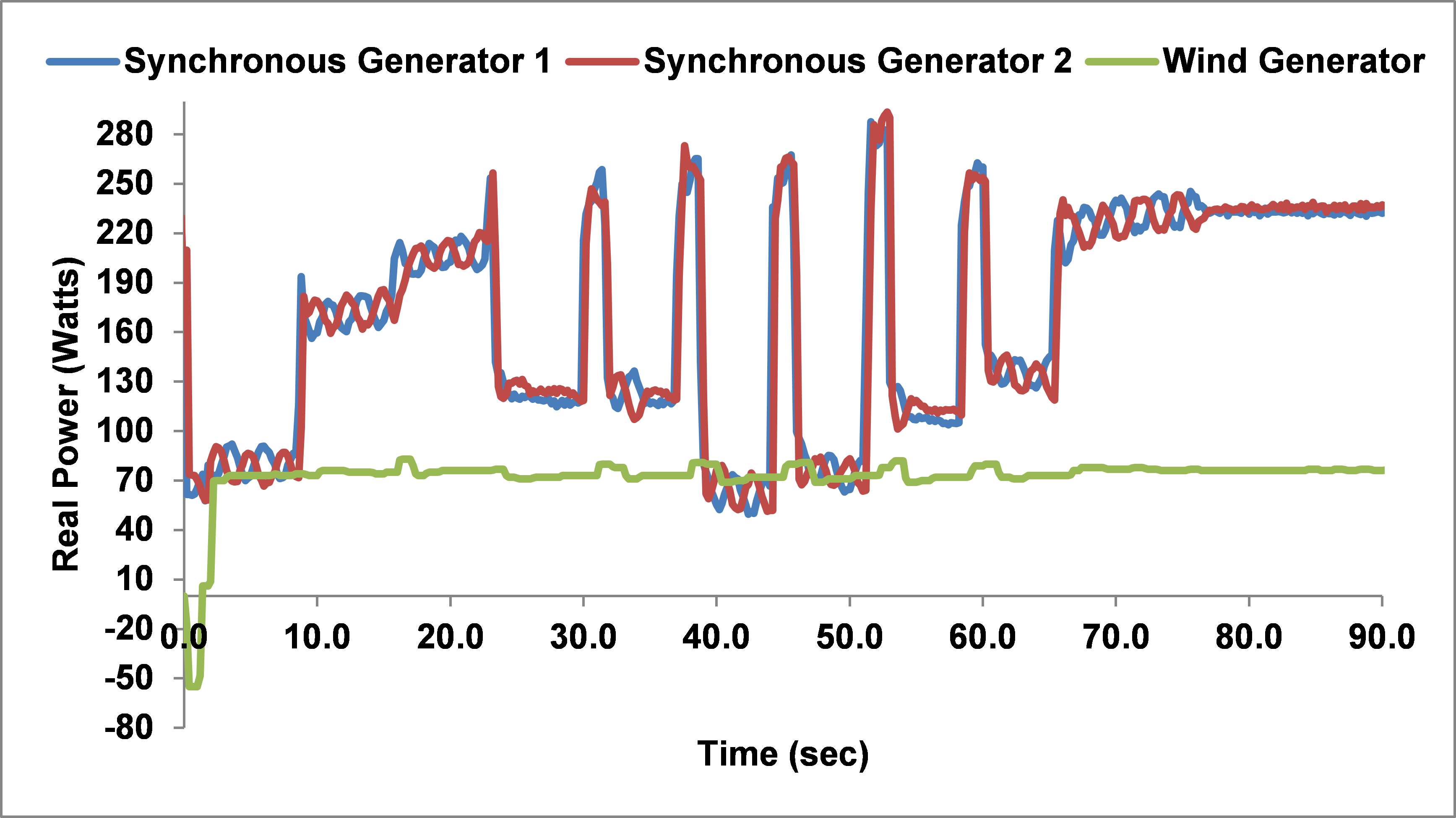
Example Project: Load Shedding
A student using two generators and the wind turbine emulator created a scenario where the load profile was too much for the total generation available and implemented a prioritized list of loads that could be shed. It is interesting to note that the fluctuations all were in the traditional generators and that the wind power was utilized throughout the study.
Note also that the dynamics caused by the load shedding are often greater than the step changes in load giving incentive to find less aggressive solutions to power shortfalls. Perhaps the rolling brown outs in California are implemented with less severe transients.
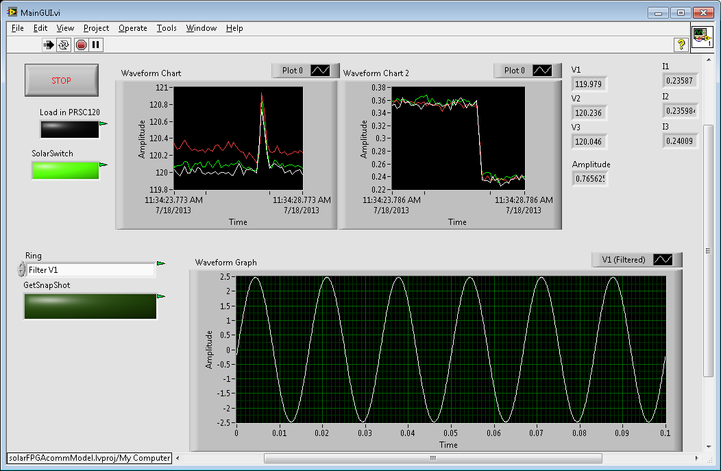
Example Project: Testing inverter design for solar emulator to a step change in load
A student developed inverter was tested using the solar panel emulator as a power source. The AC side of the microgrid was subjected to a step change in load so that the stability of the inverter could be assessed. The GUI shows a brief spike in voltage and a step change in current as a load is turned off.
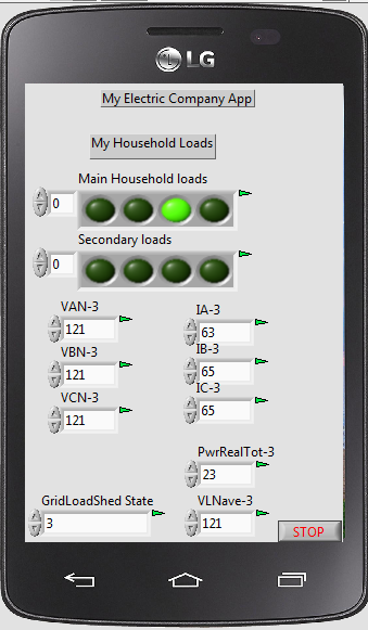
Example Project: Voluntary Customer Load Shedding through Smart Phone App
Visiting student scholars from Annamalai University in India wanted to do a small demonstration project using our laboratory. A phone app was mocked up (didn’t have time to actually write the app) whereby if a utility/customer agreement was in place, voluntary load shedding could be implemented by the utility indicating a high demand time and the consumer responding by turning off some of their loads. The smart meter can be used by the app to let the consumer know how much power they turned off and potential rewards for actively participating.